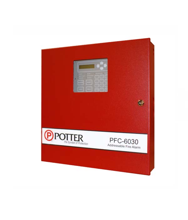
Potter Electric Signal PFC-6030 PCB PFC-6030 REPLACEMENT
BOARD
The dimensions of the PFC-6030 PCB Replacement Board are
designed to match the form factor of the original circuit board,
ensuring a proper fit within the control panel enclosure. The
dimensions may vary based on the specific model and revision of
the board.Installation: The replacement board is intended for
installation by trained technicians or professionals familiar with
electronic circuitry and control panel systems. It is important to
follow the manufacturer’s instructions and guidelines for proper
installation to ensure optimal performance and system
compatibility.Reliability and Durability: The PCB is engineered to
meet high-quality standards to ensure reliable performance and
long-term durability. It is designed to withstand the demands of
the control panel environment, including temperature variations,
electrical noise, and operational stress.Diagnostic Capabilities: The
PFC-6030 PCB Replacement Board may include diagnostic features
that enable troubleshooting and system maintenance. These
features can assist in identifying faults, errors, or malfunctions
within the control panel system, facilitating efficient repairs and
minimizing downtime.Firmware Compatibility: The replacement
board is designed to be compatible with the firmware or software
version of the PFC-6030 control panel. It ensures proper
communication and functionality between the board and other
system components, allowing for seamless integration and
operation.Regulatory Compliance: The PCB complies with
applicable safety and regulatory standards to ensure it meets
industry requirements and guidelines. This includes adherence to
electrical safety, electromagnetic compatibility (EMC), and other
relevant regulations.
Specifications
- Power Requirements: The PCB operates within a specifiedvoltage range and has power consumption specifications. It may
require a specific power supply or have power input terminals for
connection to the control panel’s power source.
- Input and Output Ports: The replacement board features variousinput and output ports for connecting external devices and sensors.
These ports may include relay outputs, input terminals for zone
connections, communication ports, and other interfaces required
for system integration.
- Memory Capacity: The PCB may include onboard memory forstoring configuration settings, event logs, or other relevant data.
The memory capacity determines the amount of data that can be
stored on the board.
- Communication Protocols: The replacement board supportsspecific communication protocols for data exchange with other
devices or systems. This may include protocols such as RS-485,
Modbus, or Ethernet for network connectivity and integration with
other control systems.
- Firmware Upgradability: The PCB may have provisions forfirmware updates to ensure compatibility with future
enhancements or bug fixes. This allows for the installation of the
latest firmware versions to maintain optimal performance and
compatibility.
- Environmental Considerations: The replacement board mayhave specified operating temperature ranges, humidity tolerances,
and protection against dust, moisture, or other environmental
factors. These specifications ensure the board’s reliability and
performance in various operating conditions.
- Certification and Compliance: The PCB may be certified orcomply with industry standards, safety regulations, and
certifications, such as UL (Underwriters Laboratories) or CE
(Conformit? Europ?ene). These certifications validate the board’s
compliance with specific safety and quality standards.
- Warranty: The replacement board may come with a warrantyperiod that covers manufacturing defects and ensures the
customer’s peace of mind. The warranty terms and conditions may
vary, so it is essential to review the manufacturer’s warranty
policy.
Features
- Advanced Diagnostic Capabilities: The replacement board mayinclude advanced diagnostic features to monitor the system’s
health and detect any faults or malfunctions. This can help with
troubleshooting and maintenance, allowing for quick identification
and resolution of issues.
- Event Logging: The PCB may have the capability to log eventsand alarms, providing a detailed record of system activity. This
feature can be valuable for system analysis, auditing, and
identifying patterns or trends in the system’s operation.
- Programmable Logic: The replacement board may offerprogrammable logic capabilities, allowing for customization and
adaptation to specific system requirements. This can involve
creating custom logic sequences, defining input-output
relationships, and implementing complex control algorithms.
- Status Indicators: The PCB may have status indicators such asLED lights or display screens that provide visual feedback about
the system’s operation. These indicators can display important
information such as power status, communication status, fault
conditions, or system modes.
- Remote Monitoring and Control: The replacement board maysupport remote monitoring and control capabilities, allowing
authorized users to access and manage the system from a remote
location. This can be achieved through network connectivity,
remote access software, or other communication methods.
- Compatibility: The replacement board is designed to becompatible with the existing system components and peripherals.
It should seamlessly integrate with the control panel, sensors,
actuators, and other devices within the system.
- Expandability: The PCB may offer expansion options toaccommodate future system expansion or integration with
additional devices. This can involve expansion slots,
communication ports, or other interfaces that allow for the
connection of supplementary modules or accessories.
- Fault Detection and Reporting: The replacement board mayinclude built-in fault detection mechanisms to detect and report
issues such as short circuits, open circuits, or communication
errors. This helps to ensure the system’s reliability and prompt
response to potential problems.
- Multiple Input and Output Configurations: The replacementboard may support various input and output configurations,
allowing for flexible system configurations and compatibility with
different types of devices and sensors.
- User-Friendly Interface: The PCB may feature a user-friendlyinterface, such as intuitive menus or a graphical user interface
(GUI), to simplify configuration, monitoring, and management
tasks. This makes it easier for users to interact with the system
and access its functionalities.


Reviews
There are no reviews yet.